Leave A Message
Dolycon offers an extensive support system to help customers choose the best product. We care about your business and personal needs. Get in touch today.

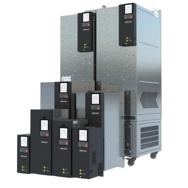


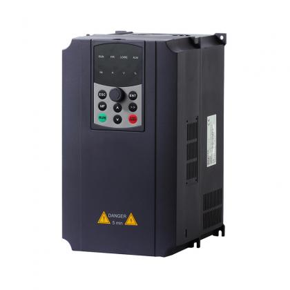
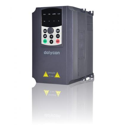
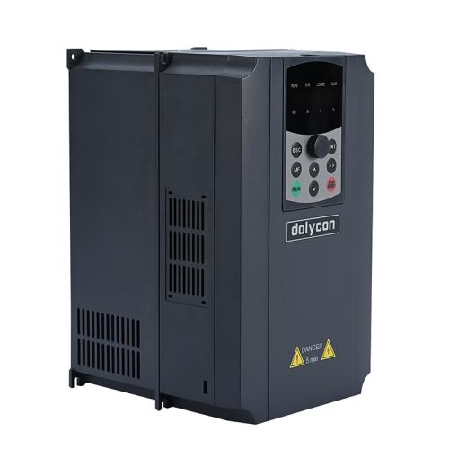
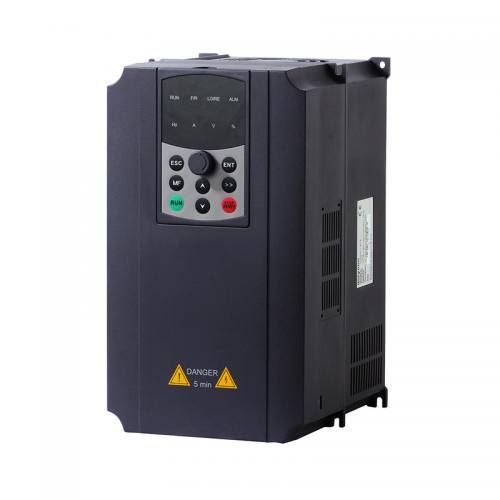
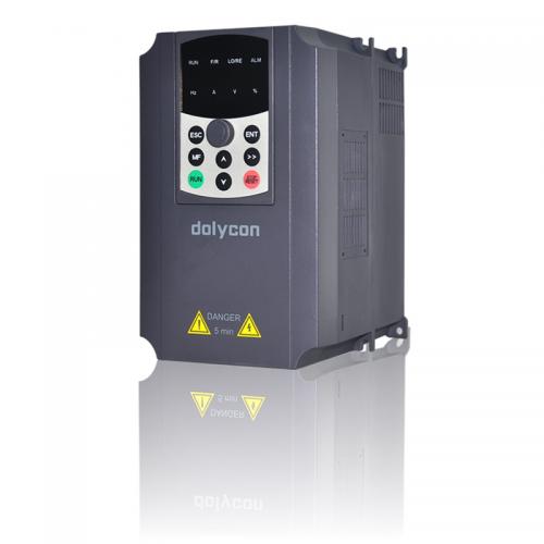
CT500 book style general purpose vfd Features:
High
performance vector control platform,
new
motor control algorithm,
supporting
open-loop and closed-loop control;
Support
to drive synchronous and asynchronous motors;
◆ Supports multiple encoders and
high-precision
closed-loop control;
◆ Supports multiple expansion cards,
customizable
for development;
Low
speed high torque,
excellent
low-speed control performance;
◆ Full series book based design,
maximizing
installation space savings;
◆ High definition LCD keyboard,
convenient for users to debug and diagnose faults;
Item NO.:
CT500 book style genThe whole machine features a three-proof design and PCB coating with three proof paint to ensure product stability and reliability. Widely applied in different fields.
 |
 |
 |
Segment code LCD screen description
 |
 |
 |
 |
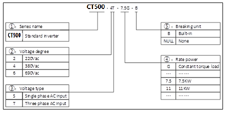
Product model name rules
Product specifications
|
Inverter mode |
Power(KW) |
Input current(A) |
Output current(A) |
Applicable motor power(KW) |
|
Three phase 380V 50/60Hz |
||||
|
CT500-4T-4.0G-B |
4.0 |
12.0 |
9.5 |
4.0 |
|
CT500-4T-5.5G-B |
5.5 |
18.5 |
14 |
5.5 |
|
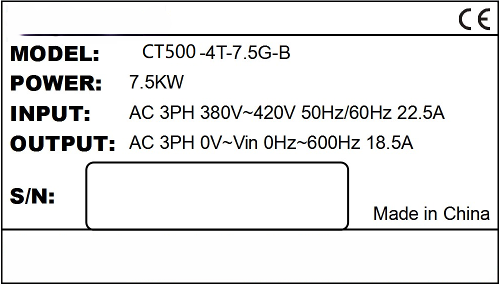
CT500-4T-7.5G-B |
7.5 |
22.5 |
18.5 |
7.5 |
|
CT500-4T-11G-B |
11 |
30.0 |
25.0 |
11 |
|
CT500-4T-15G-B |
15 |
39.0 |
32.0 |
15 |
|
CT500-4T-18.5G-B |
18.5 |
45.0 |
38.0 |
18.5 |
|
CT500-4T-22G-B |
22 |
54.0 |
45.0 |
22 |
|
CT500-4T-30G-B |
30 |
68.0 |
60.0 |
30 |
|
CT500-4T-37G-B |
37 |
84.0 |
75.0 |
37 |
|
CT500-4T-45G |
45 |
98.0 |
92.0 |
45 |
|
CT500-4T-55G |
55 |
123.0 |
115.0 |
55 |
|
CT500-4T-75G |
75 |
157.0 |
150.0 |
75 |
|
CT500-4T-90G |
90 |
188.0 |
180.0 |
90 |
|
CT500-4T-110G |
110 |
221.0 |
215.0 |
110 |
|
CT500-4T-132G |
132 |
267.0 |
260.0 |
132 |
|
CT500-4T-160G |
160 |
309.0 |
305.0 |
160 |
|
CT500-4T-185G |
185 |
344.0 |
340.0 |
185 |
|
CT500-4T-200G |
200 |
384.0 |
380.0 |
200 |
|
CT500-4T-220G |
220 |
429.0 |
425.0 |
220 |
|
CT500-4T-250G |
250 |
484.0 |
480.0 |
250 |
|
CT500-4T-280G |
280 |
539.0 |
530.0 |
280 |
|
CT500-4T-315G |
315 |
612.0 |
600.0 |
315 |
|
CT500-4T-355G |
355 |
665.0 |
650.0 |
355 |
|
CT500-4T-400G |
400 |
715.0 |
720.0 |
400 |
Note:
1. The inverter CT500-4T-160G and lower power models are able to have built-in braking unit. Among CT500-4T-37G ~ CT500-4T-160G, built-in braking unit is optional. The power and resistance of the braking resistor must meet the requirements, otherwise there is a risk of product damage. The braking units of inverter CT500-4T-185G and above power models are all external and need to be purchased by the customers.
2. The above models are standard general models and do not include special models for industry applications. Non-standard models with other specifications can be customized.
Technical parameters
| Input and output parameters | Input voltage | Single-phase 220VAC(-15%)-240VAC(+10%) |
| Three phase 380VAC(-15%)-440VAC (+10%) | ||
| Input frequency | 50~60Hz±5% | |
| Output voltage | 0~Rated input voltage | |
| Output frequency | 0~500Hz,unit0.01Hz | |
| Overload capacity | 150% of rated current:1min;180%of rated current :10s;200% of rated current:1s | |
| Running control parameters | Control mode | V/F; sensorless vector control (SVC) |
| Adjustable-speed ratio | 1:100(V/F);1:200(SVC) | |
| Speed control accuracy | ± 0.5% | |
| Speed wave | ± 0.5% | |
| Start torque | 0.5Hz/150%(V/F); 0.25Hz/150% (SVC) | |
| Based functions | Starting frequency | 0.00~10.00Hz |
| ACC and DEC time | 0.1~65000.0s | |
| Carrier frequency | 0.5KHz~16.0KHz | |
| Frequency setting | UP/DOW setting, analog setting, digital setting, multi-step speed setting, PID setting, MODBUS communication setting, to realize switch of combination and channel setting. | |
| Start mode | Start frequency, DC braking and start | |
| Stop mode | DEC stop, free stop, DEC+DC braking | |
| Energy braking capability | Braking unit braking voltage:320~750V | |
| DC braking capability | DC braking frequency: 0~500Hz; | |
| DC braking waiting time: 0~100s; | ||
| DC braking current: 0.0~100.0%; | ||
| DC braking time: 0.0~100.0s; | ||
| Auto voltage adjustment | Keep a stable output voltage automatically when the grid voltage transients | |
| Sudden frequency down | Keep stable bus voltage while power net low-voltage | |
| Control terminals | Switch input | Standard 8-channel inputs, one of which can be high-speed pulse input (HDI) |
| Analog input | Standard 2-channel inputs, AI1, AI2(0~10V or 0/4~20mA output optional) | |
| Switch output | Standard 2-channel multi-function collector outputs, one of which can be high-speed pulse output (HDO). | |
| Analog output | Standard 2-channel outputs, AO1, AO2(0~10V or 0/4~20mA output optional) | |
| Relay output | Standard 2-channel relay outputs | |
| Communication interface | RS485 Communication | RS485 communication interface for external communication, support Modbus protocol (RTU mode). |
| Fault protection | ACC overcurrent, DEC overcurrent, constant speed overcurrent, ACC overvoltage, DEC overvoltage, constant speed overvoltage, bus under voltage, motor overload, inverter overload, input power failure, output phase loss, rectifier module overheating, inverter module overheating, external fault, communication fault, current detection fault, EEPROM operation fault, PID feedback fault, factory setting time arrive etc. | |
| Keypad display | Display | Highlight segment code LCD displays the inverter information |
| Optional parts | Profibus-DP communication card, Profinet communication card, CANopen card, DeviceNet card, Modbus Tcp card, differential input PG card, UVW differential input PG card. | |
| Others | Running environment | Indoors, less than 1km above sea level, without dust, corrosive gases or direct sunlight |
| Ambient temperature | -10~+40℃, derate 1% for every additional 1℃ when the ambient temperature is between 40~50℃ | |
| Humidity | 5~95% (no condensation) | |
| Altitude | 0~2000m, derate 1% for every additional 100m when the sea level is above 1000m | |
| Vibration | Less than 0.5G | |
| Storage temperature | −40~+70℃ | |
Unit and status of LCD display
| Symbol | Name | meaning | ||
| Display area | KBD/TERM | --- | Show control inverter by keyboard or terminal or communication | |
| /COMM | ||||
| STOP/FWD/REV | --- | Show the inverter in which kind state | ||
| ALARM | --- | Light off means no fault. It is light on to show fault code, pls refer to manual | ||
| SET FREQ | Hz | It shows current setting frequency, unit is Hz | ||
| RUN FREQ / SPD | Hz/RPM | Running frequency and speed display | ||
| Users choose to display one of them | ||||
| BUS VOL | V | It shows the current bus voltage, unit is V. | ||
| OUT CUR / POW | A/Kw | Output current and power display; Users choose to display one of them. | ||
| AI1 | V/MPa | AI1 and AI2 display. It is current analog input state, display as user choose, unit is V or MPa. | ||
| AI2 | V/Mpa | |||
| DI&DO | --- | Terminal state display, DI1-DI7 and HDI input status is determined by the XX field on the right. DI1~DI7 are displayed in decimal system. Relay output 1, relay output 2, and DO status output are displayed by the X field on the left, controlled by 4 bits, and converted to hexadecimal display | ||
Functions of buttons
|
Button |
Name |
Function |
|
|
Programming/ Exit key |
Enter or exit the 1st level menu; Return to the 1st level menu from the 2nd level menu; Return to the 2nd level menu from the 3rd level menu. |
|
|
Multi-function key |
Operate according to multi-function selection [2] |
|
|
Run key |
In the keypad run command reference mode, the key is used for start control of the inverter. After setting the parameter self-identification, the key is used to start the inverter for parameter self-identification. |
|
|
Enter key |
After function group confirmation of the 1st level menu, enter the 2nd level menu; After function group confirmation of the 2nd level menu, enter the 3rd level menu; After function parameters setting confirmation of the 3rd level menu, return to the 2nd level menu; In password verification state, the password input is completed. |
|
|
Right-shift key |
Function group edit step [1] selection in the 1st/2nd level menu; Function parameters settings edit step selection in the 3rd level menu; In stop parameter display status, running parameter display status and fault display state, display parameters selection; Edit bit selection in password verification state. |
|
|
Stop/Reset key |
In keypad run command reference mode, the key is used for stop control of the inverter; In other run command reference modes, the key is used for stop protection of the inverter [3]; At fault or stop state, the key is used as a reset key to clear the fault alarm information. |
|
|
UP key |
Increase function group in the 1st/2nd level menu progressively; Increase function parameters settings in the 3rd level menu progressively; Increase the set frequency progressively. |
|
|
DOWN key |
Decrease function group in the 1st/2nd level menu progressively; Decrease function parameters settings in the 3rd level menu progressively; Decrease the set frequency progressively. |
|
|
Potentiometer |
Adjust the frequency; Adjust the torque. |
Note:
1. Select the edit step to be ones, tens or hundreds via the right-shift key.
2. See function code (F05.04) for multi-function selection.
3. After sending a stop command, you need to run the clear command in the current run command reference model
Schematic diagram of the control board
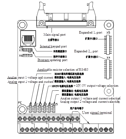
Control board terminal

Control terminal function table
| Category | Terminal name | Terminal function | Technical specification |
| Switch input | +24V | +24V power supply | 24V±10%, internal isolation from GND. max. load 200mA |
| PW | External power input terminal (power supply of digital input terminal) | Short circuit with +24V by default | |
| DI1~DI7 | Switch input terminals 1~7 | Input specifications: 24V, 5mA | |
| HDI | High speed pulse input or switch input | Pulse input frequency range: 0~50kHz | |
| High level voltage: 24V | |||
| COM | +24V power supply or external power ground | Internal isolation from GND | |
| Switch output | DO | Open collector output, common CME terminal | External voltage range: 0~24V |
| HDO | High speed pulse output or open collector output, common COM terminal | Pulse output frequency range: 0~50kHz | |
| COM | HDO common terminal | Internal isolation from GND | |
| Analog input | +10V/5V | The local supplies +10V or 5V power output | Output voltage: 10V or 5V available via X13, optional |
| Output current range: 0~50mA | |||
| (If the potentiometer is connected between +10V /5V and GND, the resistance should not be less than 2kΩ.) | |||
| AI1/AI2 | Analog input terminal 1 | Input voltage and current are optional | |
| Input voltage range: 0~10V | |||
| Input current range: 0/4~20mA | |||
| GND | Analog ground | Internal isolation from COM | |
| Analog output | AO1/AO2 | Analog output terminal | Output voltage and current are optional |
| Output voltage range: 0~10V | |||
| Output current range: 0/4~20mA | |||
| GND | Analog ground | Internal isolation from COM | |
| Relay output | T1A/TIB/TIC | Relay output | T1A-T1B: normally closed |
| T1A-T1C: normally open | |||
| Contact capacity: 250VAC/3A, 30VDC/1A | |||
| T2A/T2B/T2C | Relay output | T2A-T2B: normally closed | |
| T2C: normally open | |||
| Contact capacity: 250VAC/3A, 30VDC/1A | |||
| Communication interface | 485+/485- | RS485 communication interface | RS485 communication interface |
Product outline and installation size, weight

a) XI models
Suitable for CT500-4T-4.0G-B ~ CT500-4T-7.5G-B

b) X2 models
Suitable for CT500-4T-11G-B ~ CT500-4T-15G-B

c) X3 models
Suitable for CT500-4T-18.5G-B ~ CT500-4T-22G

d) X4 models
Suitable for CT500-4T-30G ~ CT500-4T-37G

e) X5 models
Suitable for CT500-4T-45G ~ CT500-4T-110G

f) X6 models
Suitable for CT500-4T-132G ~ CT500-4T-160G

g) X7 models
Suitable for CT500-4T-185G ~ CT500-4T-280G

g) X8 models
Suitable for CT500-4T-315G ~ CT500-4T-400G
CT500 Structure, mounting dimension and weight
| Inverter mode | Appearance and dimensions(mm) | |||||
| W | H | D | W1 | W2 | H1 | |
| CT500-2S-0.7G-B | 126 | 186 | 155 | 115 | --- | 175 |
| CT500-2S-1.5G-B | ||||||
| CT500-2S-2.2G-B | ||||||
| CT500-4T-0.7G-B | ||||||
| CT500-47-1.5G-B | ||||||
| CT500-4T-2.2G-B | ||||||
| CT500-4T-4.0G-B | 108 | 260 | 188.5 | 96 | --- | 250 |
| CT500-4T-5.5G-B | ||||||
| CT500-4T-7.5G-B | ||||||
| CT500-4T-11G-B | 128 | 340 | 180.5 | 108 | --- | 329 |
| CT500-4T-15G-B | --- | |||||
| CT500-4T-18.5G-B | 150 | 365.5 | 212.5 | 120 | --- | 348 |
| CT500-4T-22G-B | ||||||
| CT500-4T-30G-B | 180 | 436 | 203.5 | 150 | --- | 417 |
| CT500-4T-37G-B | ||||||
| CT500-4T-45G | 230 | 572.5 | 350 | 180 | --- | 550.5 |
| CT500-4T-55G | ||||||
| CT500-4T-75G | ||||||
| CT500-4T-90G | ||||||
| CT500-4T-110G | ||||||
| CT500-4T-132G | 280 | 652.5 | 366 | 246 | --- | 632.5 |
| CT500-4T-160G | ||||||
| CT500-4T-185G | 330 | 1252.5 | 522.5 | 250 | --- | --- |
| CT500-4T-200G | ||||||
| CT500-4T-220G | ||||||
| CT500-4T-250G | ||||||
| CT500-4T-280G | ||||||
| CT500-4T-315G | 360 | 1275 | 546.5 | 250 | --- | --- |
| CT500-4T-355G | ||||||
| CT500-4T-400G | ||||||
CT100F PMSM vector control inverter adopts original magnetic pole detection technology to realize soft-start, no reverse, or joggle, meet high requirement application.
CT100G series General Purpose Frequency Inverter is based on the DSP control system, has high-performance open-loop vector control technology, achieving excellent performance and high reliability. It can be applied to asynchronous motors, providing excellent drive performance.
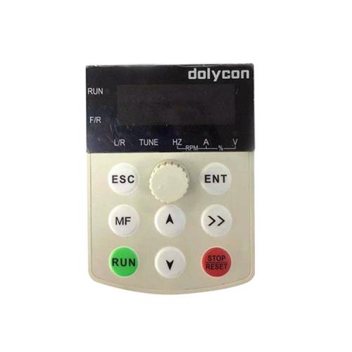
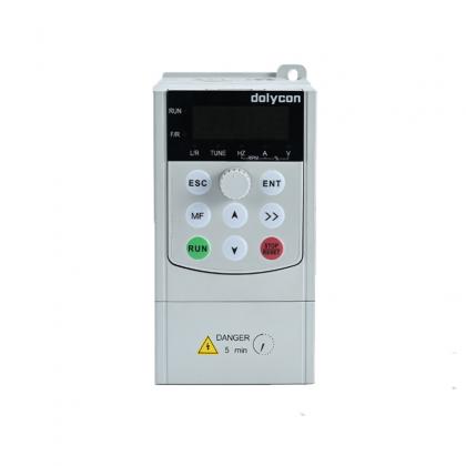
Control panel keypad with LCD display for VFD local or remote use.
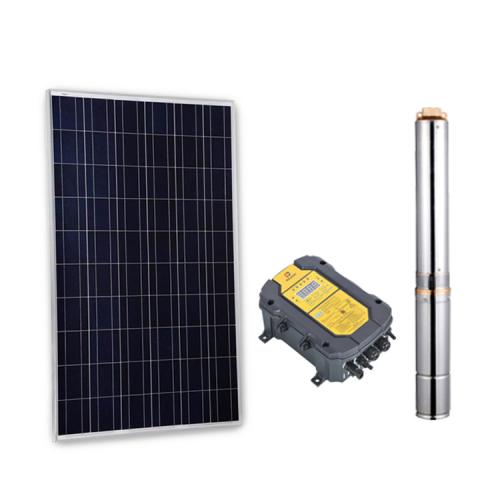
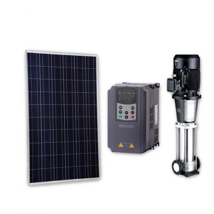
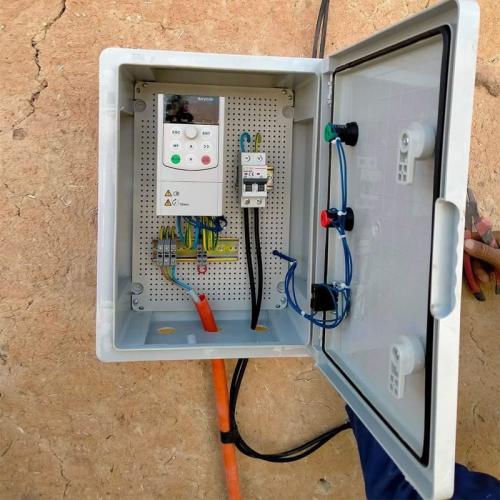
Dolycon solar pump inverter uses solar energy as power to drive water pumps to pump water from seed wells, river, lakes, reservoirs, and other water sources. The system mainly contains three parts: solar panel, solar pump inverter, and water pump.
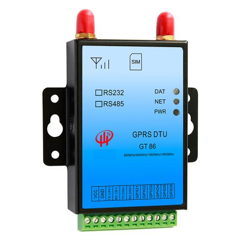
GT86 GPRS is a wireless date transmission terminal based on GPRS network,provides transparent date channel, can facilitate the realization of the remote, wireless and network communication. Make it easy for your device with Internet to connect by wireless. GT86 has a wide range of network coverage (it can be used anywhere you can use mobile phones), flexible and fast networking (installation can be used), low operation cost (billing according to the flow) etc. Meanwhile a high precision GPS chip has been embedded into GT86, it can real-time supply the location information of product.
CT100 series general purpose VFD based on DSP control system, has high performance open loop vector control technology,achieving excellent performance and high reliability. It can be applied to asynchronous motors, providing excellent drive performance. Shenzhen Dolycon Technology Co., LTD Founded in 2015, we have been focusing on the research, development and sales of variable frequency drives and solar water pump inverters for more than 7 years. We are a national high-tech and professional manufacturer of various variable frequency drives and solar water pump inverters.

VFD control panel keyboard, easy to install and use. With multiple inputs and outputs, power and speed can be adjusted through this vfd module.
CT112M mini series solar pump inverter is a small power inverter converter solar panel dc to ac power, specially for AM or PMSM solar pump control.


 IPv6 network supported


 English
 فارسی
فارسی français
 русский
 español
 português
 العربية
 Türkçe
 ไทย
ไทย Tiếng Việt